The Core Concept
Loading 3D Model...
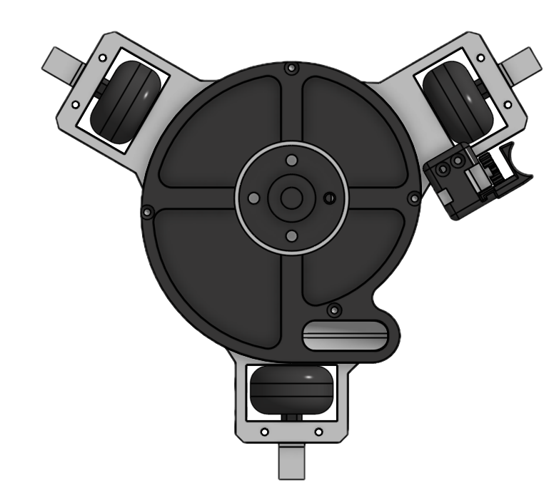
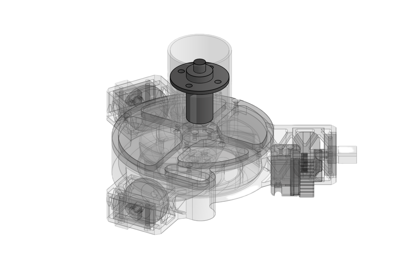
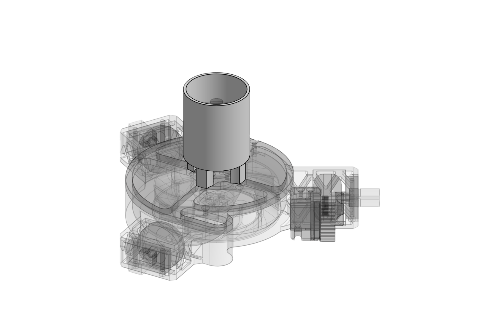
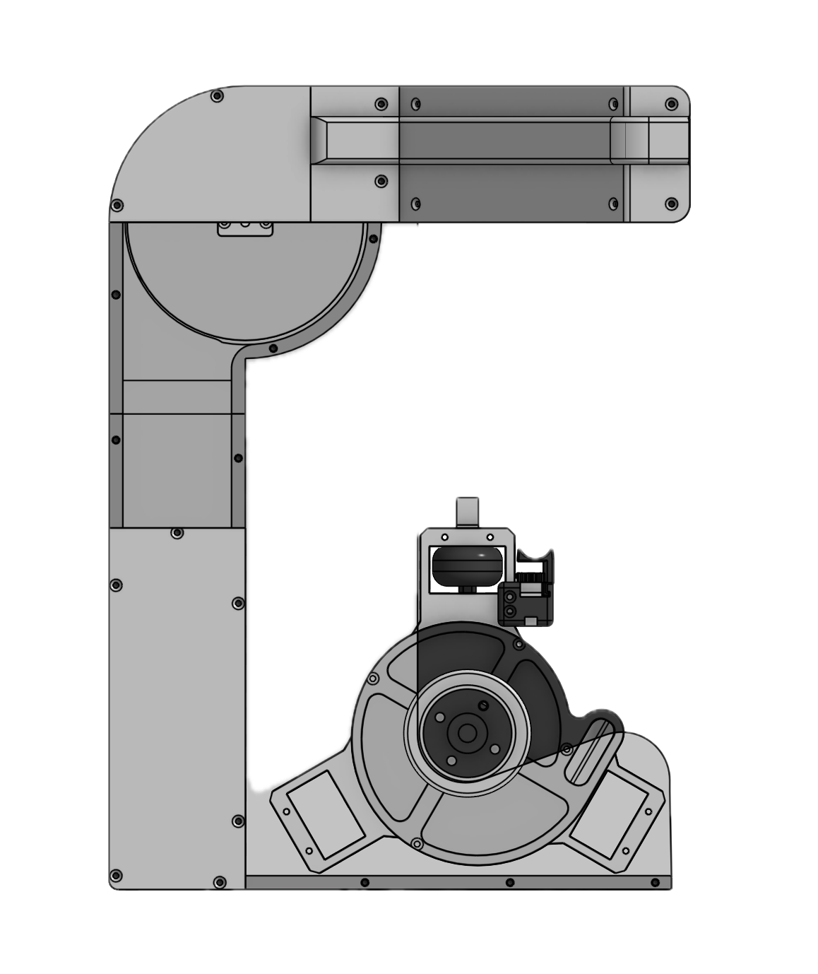
Full Robot AssemblyWe're building a wall-climbing robot that uses suction to create a vacuum (pressure differential) between the window and the robot itself. The robot adheres to the window using an impeller and uses an external marker mechanism to draw on vertical surfaces.
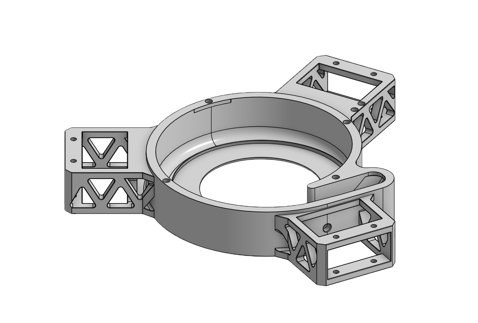
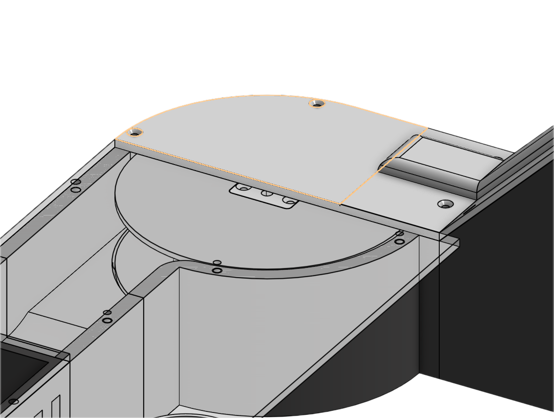
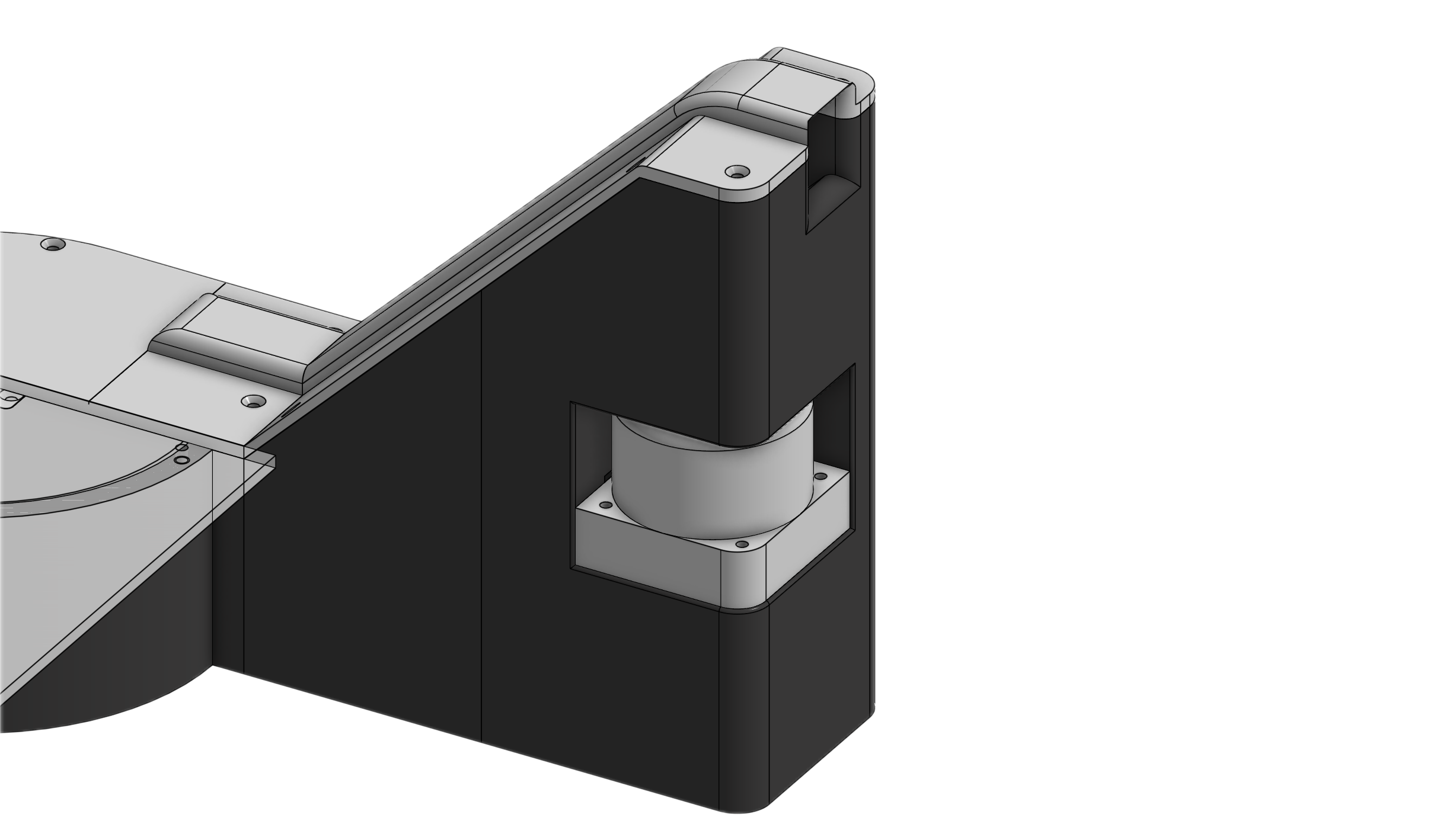
Chassis
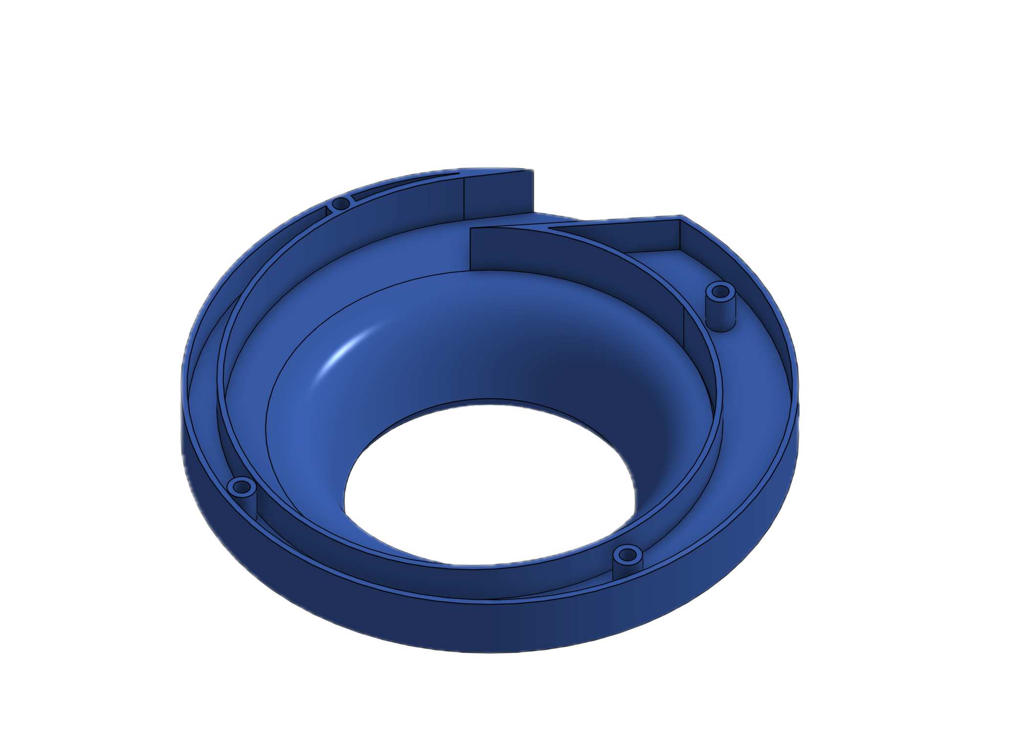
Lightweight 3D-printed frame with integrated shrouding
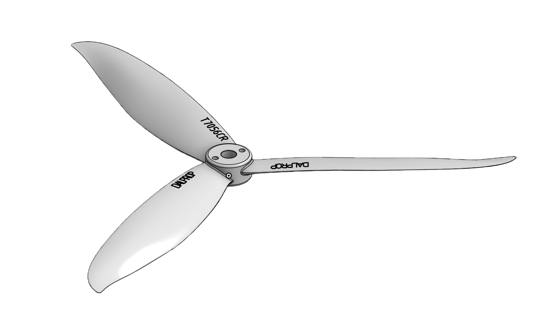
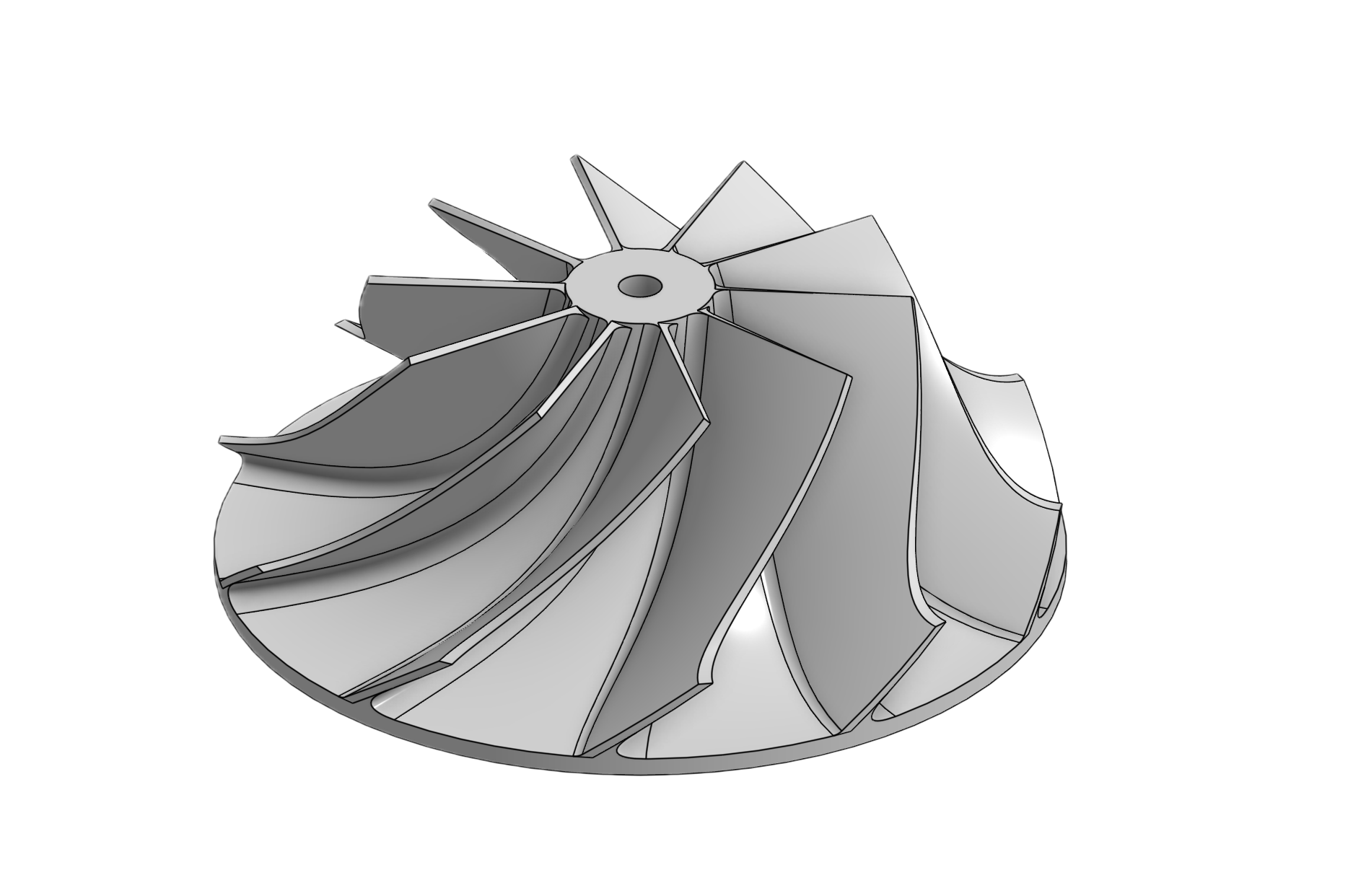
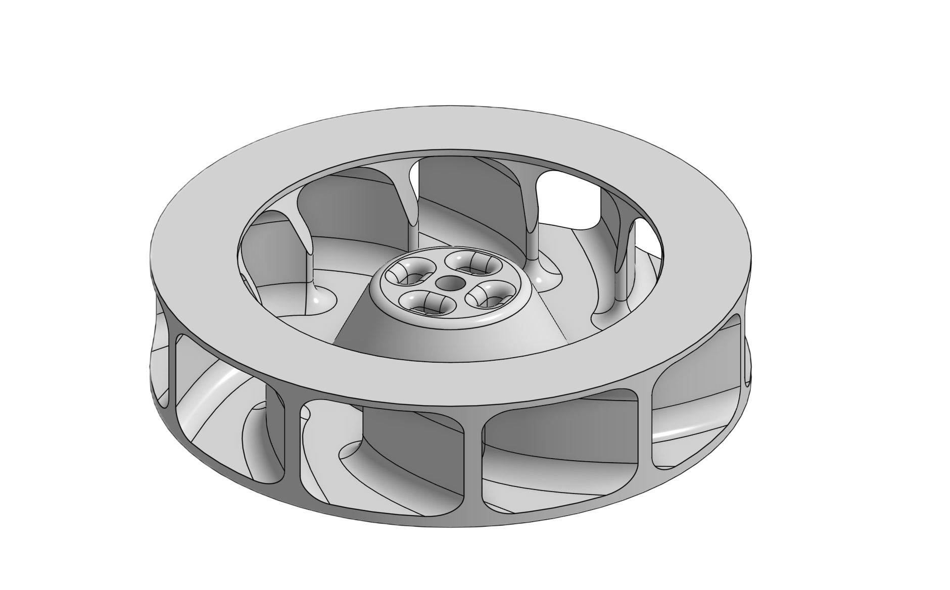
Impeller
CFD-optimized centrifugal design for maximum suction
Kiwi Drive
Three omni-wheels for omnidirectional movement
Tether System
360° slip ring with motorized spool management